
Occasionally, a third hand is needed off lathe for sanding, embellishment and/or carving.
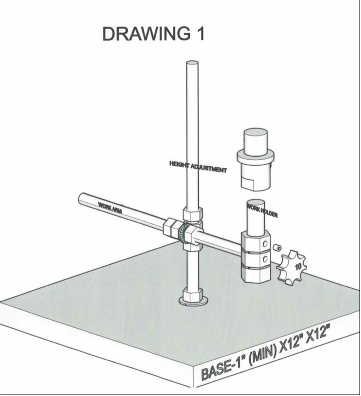
This article gives assembly instructions for a third hand (drawing 1). This device allows the craftsman to manipulate a piece of work off lathe, which makes manipulating the piece much easier. The cost to fabricate the device is around $50.00.
Material:
- Base – Wood, 1" (min) x 12" x 12"
- Coarse (20 tpi) Threaded rod, ½" dia. x 24" long
- Hex nut, ½" coarse (20 tpi) thread – 8 each
- Hex nut, ¾" coarse (10 tpi) – 2 each
- Washer, split, ½" – 2 each
- Washer, flat metal, ½"- 2 each
- Washer, flat plastic, ¾" – 2 each
- Set screw or hex bolt, ¼" coarse (20 tpi) thread x ½" long – 1 each
- Bolt, hex head, ¼" coarse (20 tpi) x 1 ¼" long – one each
- Bolt, hex head, ¾" coarse (10 tpi) x 3" long – 1 each
- Spindle adapter, ¾" 10 tpi x 1” 8 tpi
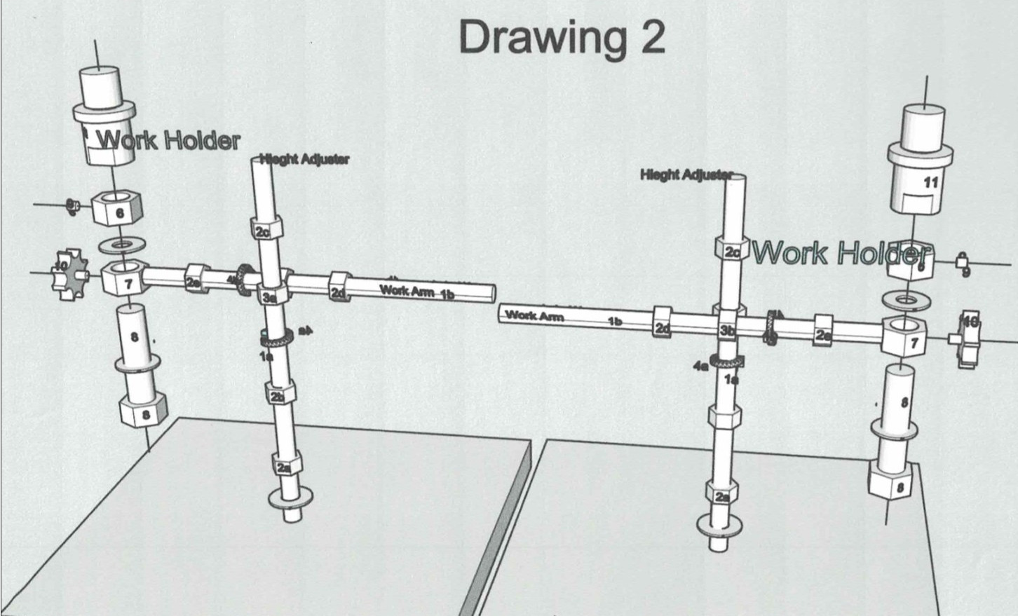
Preparation (drawing 2): Note – numbers in parenthesis below refer to the part in drawing 2.
- Drill the threads out of 2 of the ½" hex nuts.
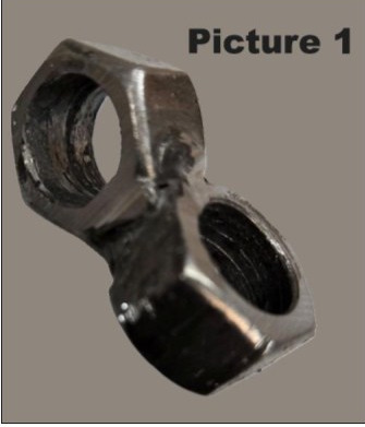
- Weld the dethreaded hex nuts together with the nuts at 90 degrees to each other. (picture 1), (3)
- Drill out the threads in one of the ¾" hex nuts.
- In the center of a flat face in both ¾" hex nuts, drill and tap a hole for ¼" coarse threads. (6,7).
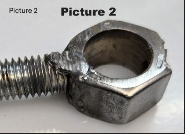
 Cut the ½" threaded rod into 12" (1a) and 10" (1b) lengths.
- Weld the flat opposite the threaded hole of de-threaded ¾" hex nut (7) to the end of the 10" length (1b) of threaded rod. (picture 2.)
 Cut the ½" threaded rod into 12" (1a) and 10" (1b) lengths.
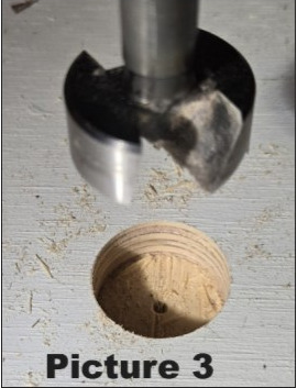 Weld the flat opposite the threaded hole of de-threaded ¾" hex nut (7) to the end of the 10" length (1b) of threaded rod. (picture 2.)
Height Adjuster Assembly (Refer to drawing 2 )
- In the middle of the base, drill a counter sink with a 1 ¼" Forstner bit or spade bit ½" deep. This side of the base will be the bottom. (picture 3)
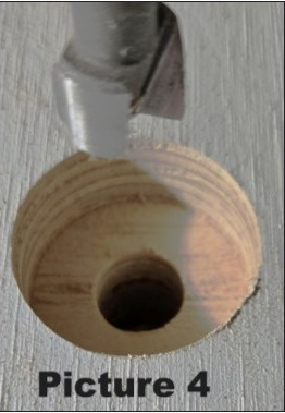
- Drill a ½" hole in the middle of the counter sink through the base to the top of the base (picture 4)
- Thread a ½" nut (2a) and a ½" metal washer on the end of the 12" length of threaded rod (1a) and insert the end of the rod below the washer through the ½" hole in the top of the base. Limit the amount of rod in the bottom to the depth of the counter sink. (picture 5)
- In the bottom of the base place a ½" metal washer around the threaded rod (1a) followed by threading a ½" hex nut onto the rod after the washer. (picture 6). This rod is the Height Adjuster Rod.
- Tighten both nuts to secure the rod to the base.
- Thread a ½" hex nut (2b) onto the Height Adjuster rod to about the middle of the rod.
- Slide a ½" split washer onto the rod to the nut (2b).
- Slide the de-threaded ½" welded nut assembly (3 a) down onto the split washer. (picture 7).
- Thread a ½" hex nut (2c) onto the Height Adjuster rod (1a) down to the top of the welded nut (3a) and tighten snuggly. (picture 8)
 In the middle of the base, drill a counter sink with a 1 ¼" Forstner bit or spade bit ½" deep. This side of the base will be the bottom. (picture 3)
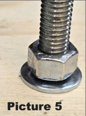 Drill a ½" hole in the middle of the counter sink through the base to the top of the base (picture 4)
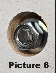 In the bottom of the base place a ½" metal washer around the threaded rod (1a) followed by threading a ½" hex nut onto the rod after the washer. (picture 6). This rod is the Height Adjuster Rod.
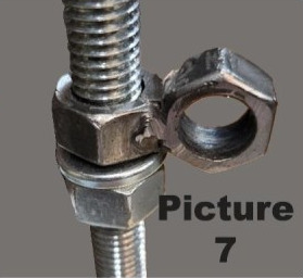 Thread a ½" hex nut (2b) onto the Height Adjuster rod to about the middle of the rod.
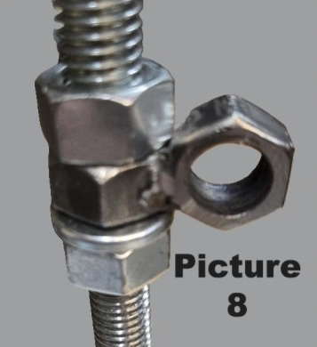 Slide the de-threaded ½" welded nut assembly (3 a) down onto the split washer. (picture 7).
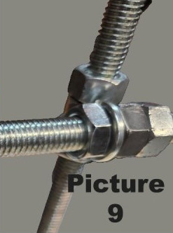 Thread a ½" hex nut (2c) onto the Height Adjuster rod (1a) down to the top of the welded nut (3a) and tighten snuggly. (picture 8)
Work Arm Assembly
- Thread a ½" hex nut (2e) about halfway onto the 10" threaded rod (1b) welded to ¾" hex nut (7).
- Follow the hex nut (2e) with a ½" split washer.
- Slide the threaded rod (1b) through the welded de-threaded ½" hex nut (3b) to the split washer. (picture 9)
- Thread a ½" hex nut (2d) onto the 10" threaded rod to the opposite side of the welded nut (3b) and tighten snuggly. (picture 9).
 Thread a ½" hex nut (2d) onto the 10" threaded rod to the opposite side of the welded nut (3b) and tighten snuggly. (picture 9).
Work Holder Assembly
- Slide a ¾" plastic flat washer on to the ¾" bolt (8) to the head of the bolt.
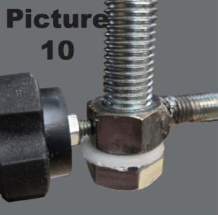
- Thread the ¼" x 1 ¼" bolt (10) into the ¼" threaded hole in the side of the ¾" welded hex nut (7) for 1-2 threads.
- Slide the ¾" hex bolt (8) with plastic washer all the way into the ¾" welded hex nut (7) up to the nut. Tighten the ¼" bolt (10) into the side of the hex nut (7). (picture 10)
- Slide a plastic flat washer onto the end of the ¾" bolt (8) to the opposite side of the welded ¾" hex nut (7).
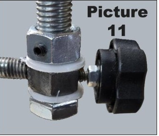
- Thread the threaded ¾" hex nut (6) onto the end of the bolt all the way to the plastic washer. (picture11)
- Insert the ¼" set screw or, alternately the ¼" diameter x ½" long bolt (9) into the ¼" threaded hole in the threaded ¾" hex nut(6). Tighten slightly. (picture 11)
- Loosen the ¼" bolt (10) in the welded ¾" nut (7) to a point where it is not jamming the ¾" bolt.
- Loosen the ¾" set screw or bolt (9) in the threaded ¾" hex screw (6) and turn this nut to adjust the spacing between the head of the bolt, the welded hex nut and the ¾" threaded nut so that the bolt turns but have very little other movement. Tighten the set screw or bolt (9) in the threaded ¾" hex nut (6) onto the threaded of the ¾" bolt (8).
- Thread the spindle adapter (11) onto the end of the ¾" bolt (8) until the adapter bottoms out. Tighten the adapter snuggly. (picture 12)
 Thread the ¼" x 1 ¼" bolt (10) into the ¼" threaded hole in the side of the ¾" welded hex nut (7) for 1-2 threads.
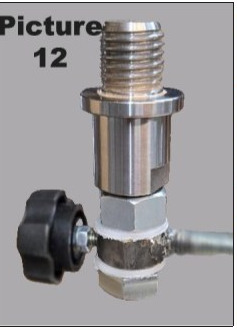 Thread the threaded ¾" hex nut (6) onto the end of the bolt all the way to the plastic washer. (picture11)
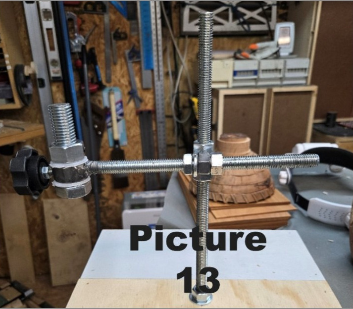 Loosen the ¾" set screw or bolt (9) in the threaded ¾" hex screw (6) and turn this nut to adjust the spacing between the head of the bolt, the welded hex nut and the ¾" threaded nut so that the bolt turns but have very little other movement. Tighten the set screw or bolt (9) in the threaded ¾" hex nut (6) onto the threaded of the ¾" bolt (8).
The completed assembly is shown in picture 13.
Operation
The height of the work arm is adjusted by loosening the ½" hex nut (2b or 2c) above or below the welded ½" hex nut (3a) on the vertical threaded rod (1a) and sliding the work arm up or down to the desired height. The nuts (2b,2c) on the height adjustment assembly are tightened.
The work arm is adjusted in or out by loosening the ½" nuts (2d,2e) on the work arm and sliding the arm in or out to the desired length. Rotating the work head is done in the same way. The ½" nuts (2d,2c) on the work arm are then tightened to stay the work head.
The work on the work head may be rotated or stayed by loosening or tightening, respectfully, the ½" bolt (10) threaded in the welded ¾" nut (7).