Featured Posts

Making a Stop Block for Your Saw(S)
Making a Stop Block for your Saw(s) by Bob Grinstead
Here is an easy to make “Stop Block” for your table saw or bandsaw.
Needed:
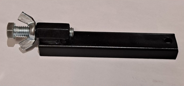
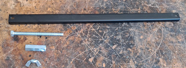
- (1) magnetic tool bar (Harbor Freight, 18″ magnetic tool bar)
- (1) 3/8″ coupling
- (1) 3/8″ nut
- (1) 3/8″ x 4″ bolt
- (1) 3/8″ wingnut
- (1) 3/8” washer
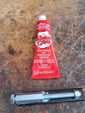
- Shoe Goo (glue)
- Paint
Assembly:
-
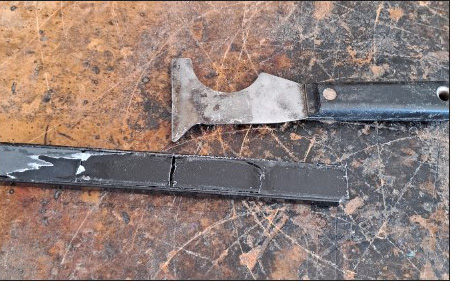
There are 8 individual magnets in the bar. They are covered with a thin layer of tape. Each magnet is about 2″ long.
In some bars the magnets are loose, you can just take a knife and separate two magnets from the rest leaving room at the end for the hole or cut a slot for a screwdriver.
In other bars the magnets are glued in place. Place one end of the bar in a vice and using any tool, crescent wrench, twist the bar a little in both directions. The glue is hard. This will break the glue/magnets loose. Remove the magnets and clean them and the bar up. I used a sanding block to remove the glue.

Cut the steel bar into equal parts if you want to make several. A hole or slot is cut into one end of each piece of bar to easily remove the stop block from your table.
- I made several to give away. One bar will make 4 stop blocks.
- Remove the burrs with a file or grind it smooth.
- Remove the paint from the end of the bar opposite the hole or screwdriver slot you have made to help the glue stick.
- Roughen up the surface of both the coupling and the bar where the glue will meet.
- Move (2) magnets flush to this end of the bar, opposite the hole.
- Take a long 3/8″ bolt and run it all the way down on the coupling.
- Thread the nut on the other end of the bolt. The nut is for support and alignment while the glue dries.
- Put some glue on the coupling and press it on the flat surface of the bar opposite the hole. Make sure the coupling extends a little past the bar. This will become the seat for the wingnut.
- Once the glue dries, remove the nut and bolt.
- Paint
- Sand or grind the head of the bolt smooth
- Put the washer on the bolt and screw the wingnut on the bolt with the wings toward the head of the bolt. Screw the bolt into the coupling.
To use:
Place the Stop Block on your steel table bed, using the head of the bolt as a stop that is adjustable. The wing nut will tighten the bolt to the coupling and not let it move once it is adjusted correctly.
To remove the Stop Block:
Tilt the bar on its long edge or place a screwdriver in the hole/slot and tilt the bar up on its long edge. This will break the tension of the magnets.
CLICK TO CONTINUE

Come join us having fun turning wood into a custom wonder.